Copper-foil 4-element Yagi-Uda
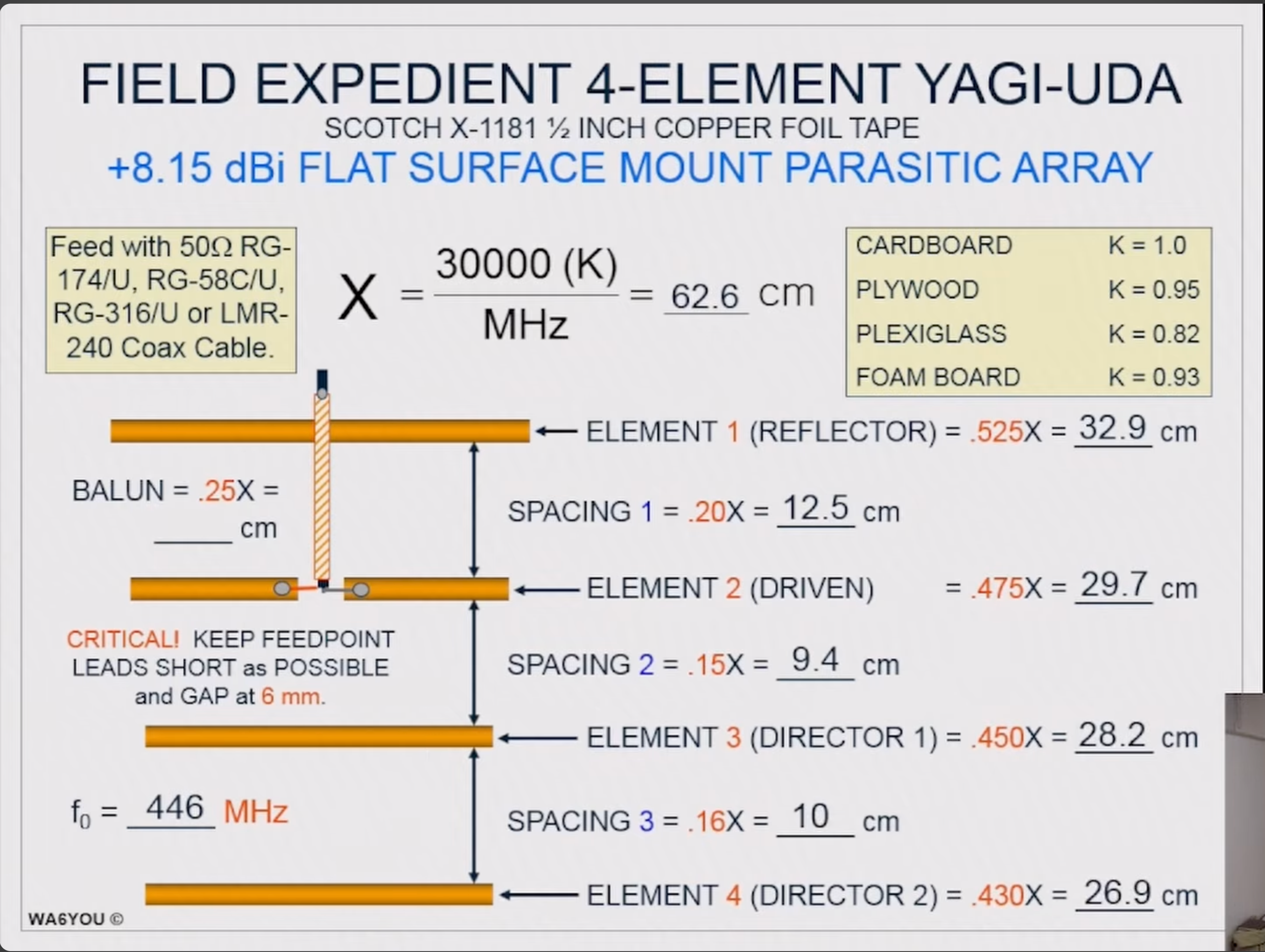
A field-expedient flat-surface array by WA6YOU — about +8.15 dBi. This page is a calculator for his multipliers, not a claim on the design. Tape is Scotch X-1181 ½-inch copper foil. Charts from Field expedient Yagi-Uda antenna with Ron Payne, WA6YOU.
| Piece | Length |
|---|---|
| X (30000 × K / MHz) | — |
| Element 1 · reflector (0.525 X) | — |
| Spacing 1 · reflector to driven (0.20 X) | — |
| Element 2 · driven (0.475 X) | — |
| Spacing 2 · driven to director 1 (0.15 X) | — |
| Element 3 · director 1 (0.450 X) | — |
| Spacing 3 · director 1 to 2 (0.16 X) | — |
| Element 4 · director 2 (0.430 X) | — |
| Balun · ¼-wave sleeve (0.25 X) | — |
| Boom (sum of spacings) | — |
Build notes
- Feed with 50 Ω RG-174/U, RG-58C/U, RG-316/U, or LMR-240.
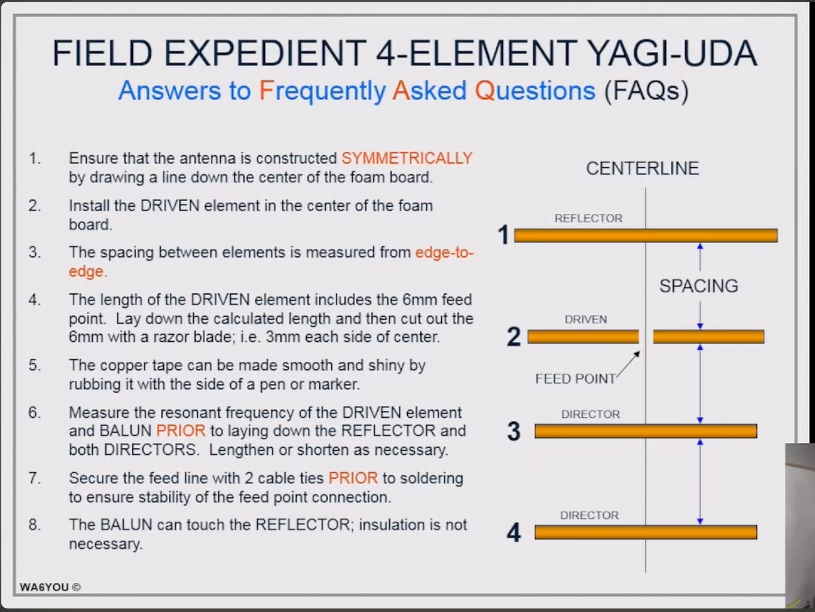
- Draw a centerline down the board and build the antenna symmetrically about it.
- Put the driven element at the center of the board, then lay the other elements out from there.
- Measure each spacing from edge to edge.
- The driven-element length includes the 6 mm feed gap. Stick down the calculated length, then cut out 6 mm with a razor — 3 mm each side of the centerline.
- Rub the foil with the side of a pen or marker if you want it smooth and shiny.
- Check the driven element and the balun on frequency before you lay the reflector and both directors. Lengthen or shorten as needed.
- Tie the feed line down with two cable ties before you solder, so the joint cannot move.
- The sleeve may touch the reflector. No insulation is required there.
- WA6YOU’s worked example on the original chart is 446 MHz on foam board (K = 0.93), which gives X = 62.6 cm.
WA6YOU construction FAQ
Feeding the driven element
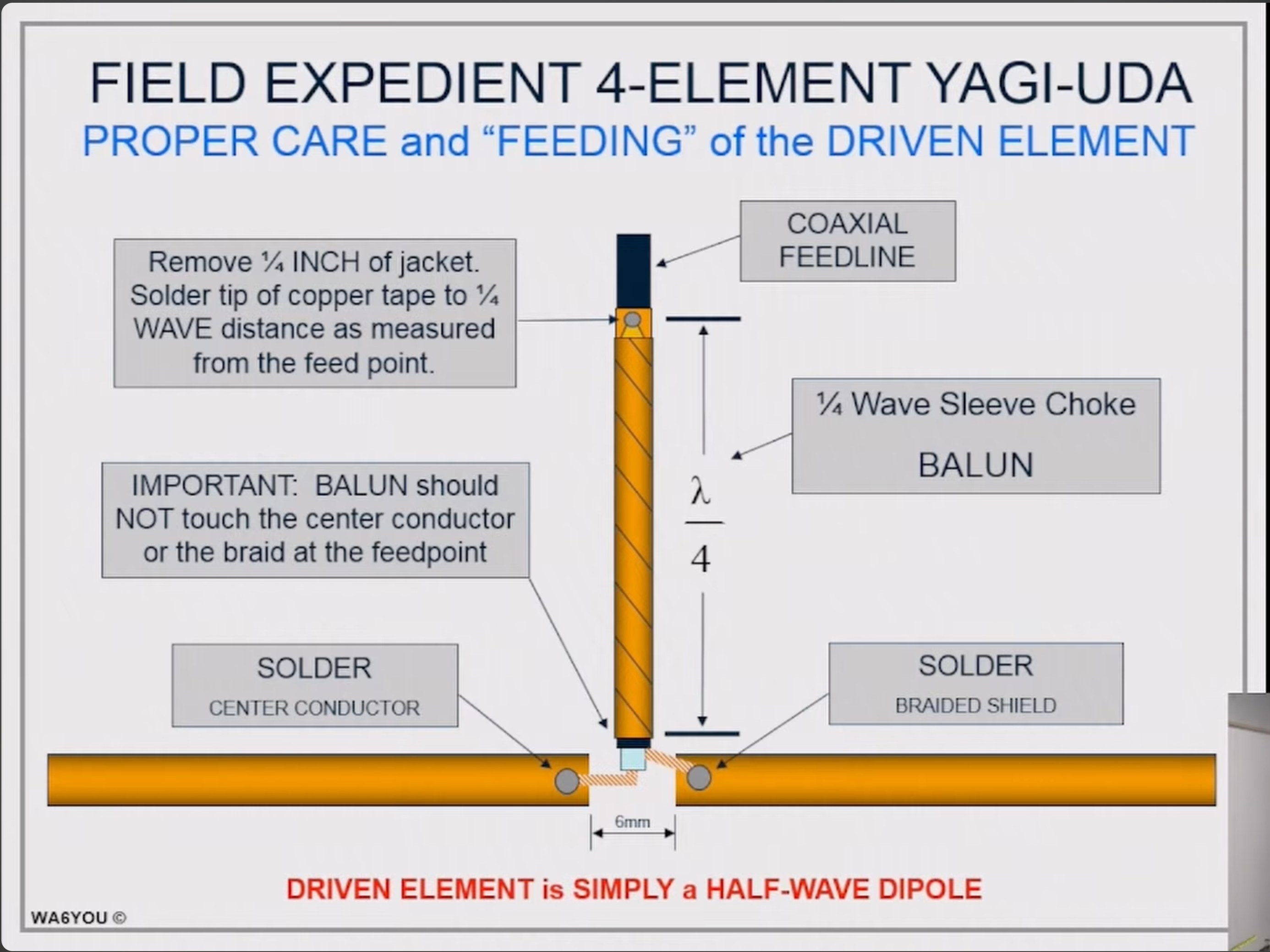
WA6YOU feeds this antenna with a bazooka. The outer conductor is the same Scotch copper-foil tape as the elements, wrapped in a spiral around the coax jacket for a quarter wave — 0.25 X on his chart. The 45° lines on his feed drawing are that wrap of tape, not a hatch. This page calculates his design; it does not claim it.
The tape is bonded to the coax braid at the far end. That joint is the short. The sleeve and the outside of the braid are then a shorted quarter-wave stub. A quarter-wave line transforms a short into an open circuit, so a quarter wave away, at the feed, the outside of the braid looks like a high impedance. Common-mode current coming back down the outside sees that high impedance and is choked. The inside of the coax, between the center conductor and the inside of the braid, still carries the feed.
- The driven element is a half-wave dipole. Leave a 6 mm gap at its center.
- Measure 0.25 X back from that feedpoint. Remove ¼ inch of jacket there and solder the tip of the copper tape to the braid. That joint is the short.
- From that short, spiral the copper-foil tape around the jacket back toward the antenna. The 45° lines on the chart are the edges of this wrap. The wrap is the quarter-wave sleeve, 0.25 X.
- Stop the sleeve short of the feedpoint. It must not touch the center conductor or the braid there. That open end is where the outside of the braid is a high impedance.
- Solder the center conductor to one side of the gap and the braided shield to the other. Keep those leads short.
WA6YOU feed chart
Original WA6YOU diagram